logo

CuriousTab

CuriousTab

Describing Logic Circuits problems


  • 1. The OR gate performs like two switches wired in a series.

  • Options
  • A. True
  • B. False
  • Discuss
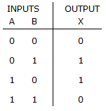
  • 2. The truth table shown below describes the operation of a NOR gate.

    Digital Electronics Describing Logic Circuits: The truth table shown below describes the operation of a NOR gate.


  • Options
  • A. True
  • B. False
  • Discuss
  • 3. The given figure shows the correct logic implementation of the distributive law.

    Digital Electronics Describing Logic Circuits: The given figure shows the correct logic implementation of the distributive law.


  • Options
  • A. True
  • B. False
  • Discuss
  • 4. Boolean multiplication is symbolized by A + B.

  • Options
  • A. True
  • B. False
  • Discuss
  • 5. The comments in ADHL are enclosed between # characters.

  • Options
  • A. True
  • B. False
  • Discuss
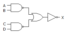
  • 6. The figure given below is an example of the implementation of AND-OR-INVERT logic.

    Digital Electronics Describing Logic Circuits: The figure given below is an example of the implementation of AND-OR-INVERT logic.


  • Options
  • A. True
  • B. False
  • Discuss
  • 7. In VHDL, local signals are declared in the VARIABLE section, which is placed between the SUBDESIGN section and the logic section.

  • Options
  • A. True
  • B. False
  • Discuss
  • 8. NOR gates can be used to construct AND gates.

  • Options
  • A. True
  • B. False
  • Discuss
  • 9. The SUBDESIGN section defines the input and output of the logic circuit block.

  • Options
  • A. True
  • B. False
  • Discuss

First 2 3 4 5 6