logo

CuriousTab

CuriousTab

Discussion


Home Digital Electronics Describing Logic Circuits Comments

  • Question
  • The given figure shows the correct logic implementation of the distributive law.

    The given figure shows the correct logic implementation of the distributive law. True False


  • Options
  • A. True
  • B. False

  • Correct Answer
  • True 


  • Describing Logic Circuits problems


    Search Results


    • 1. The truth table shown below describes the operation of a NOR gate.
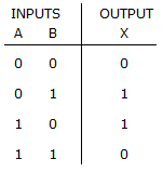

    • Options
    • A. True
    • B. False
    • Discuss
    • 2. The OR gate performs like two switches wired in a series.

    • Options
    • A. True
    • B. False
    • Discuss
    • 3. The application of DeMorgan's theorems to a Boolean expression with double and single inversions produces a resultant expression that contains only single inverter signs over single variables.

    • Options
    • A. True
    • B. False
    • Discuss
    • 4. The expressions, , are equivalent.

    • Options
    • A. True
    • B. False
    • Discuss
    • 5. Output logic levels for certain input conditions of a logic circuit may often be determined without using the Boolean expression.

    • Options
    • A. True
    • B. False
    • Discuss
    • 6. Boolean multiplication is symbolized by A + B.

    • Options
    • A. True
    • B. False
    • Discuss
    • 7. The comments in ADHL are enclosed between # characters.

    • Options
    • A. True
    • B. False
    • Discuss
    • 8. The figure given below is an example of the implementation of AND-OR-INVERT logic.
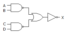

    • Options
    • A. True
    • B. False
    • Discuss
    • 9. In VHDL, local signals are declared in the VARIABLE section, which is placed between the SUBDESIGN section and the logic section.

    • Options
    • A. True
    • B. False
    • Discuss
    • 10. NOR gates can be used to construct AND gates.

    • Options
    • A. True
    • B. False
    • Discuss


    Comments

    There are no comments.

Enter a new Comment