CuriousTab |
CuriousTab
Discussion
Home ‣ Digital Electronics ‣ Logic Gates See What Others Are Saying!
- Question
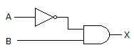
The gates in this figure are implemented using TTL logic. If the output of the inverter is open, and you apply logic pulses to point B, the output of the AND gate will be ________.
Options- Correct Answer
- pulses
- 2. Which of the figures given below represents a NOR gate?
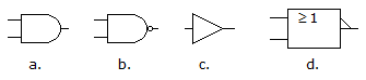
Options
Discuss
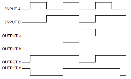
- 4. For a two-input XNOR gate, with the input waveforms as shown below, which output waveform is correct?
Options
Discuss
- 8. For the SOP expression
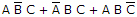 , how many 1s are in the truth table's output column?
Options
Discuss
More questions
Correct Answer: d
Correct Answer: d
Correct Answer: 3
Comments
There are no comments.