CuriousTab |
CuriousTab
Discussion
Home ‣ Digital Electronics ‣ Combinational Logic Circuits Comments
- Question
For a two-input XNOR gate, with the input waveforms as shown below, which output waveform is correct?
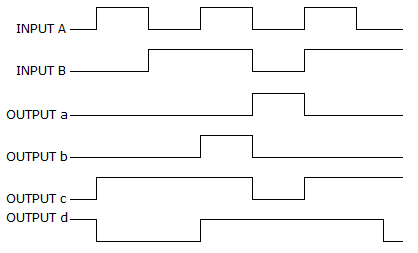
Options- Correct Answer
- d
- 1. The simplest equation which implements the K-map shown below is:
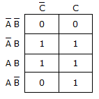
Options- A.

- B.

- C.
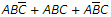
- D.
 Discuss
- 6. Which of the K-maps given below represents the expression X = AC + BC + B?
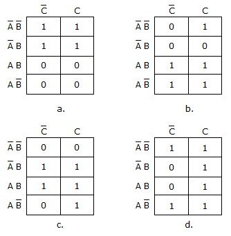
Options
Discuss
- 7. Which of the following logic expressions represents the logic diagram shown?
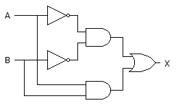
Options- A.

- B.

- C.

- D.
 Discuss
- 8. Based on the indications of probe A in the figure given below, what is wrong, if anything, with the circuit?
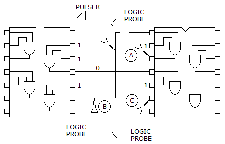
Options
Discuss
- 9. The device shown here is most likely a ________.
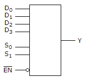
Options
Discuss
Combinational Logic Circuits problems
Search Results
Correct Answer:
Correct Answer: c
Correct Answer:
Correct Answer: Nothing appears to be wrong at that point.
Correct Answer: multiplexer
Comments
There are no comments.