logo

CuriousTab

CuriousTab

Discussion


Home Digital Electronics Counters Comments

  • Question
  • A MOD-12 and a MOD-10 counter are cascaded. Determine the output frequency if the input clock frequency is 60 MHz.


  • Options
  • A. 500 kHz
  • B. 1,500 kHz
  • C. 6 MHz
  • D. 5 MHz

  • Correct Answer
  • 500 kHz 


  • Counters problems


    Search Results


    • 1. For a multistage counter to be truly synchronous, the ________ of each stage must be connected to ________.

    • Options
    • A. Cp, the same clock input line
    • B. CE, the same clock input line
    • C. , the terminal count output
    • D. , both clock input lines
    • Discuss
    • 2. Which segments (by letter) of a seven-segment display need to be active in order to display a digit 6?

    • Options
    • A. b, c, d, e, f, and g
    • B. a, c, d, e, f, and g
    • C. a, b, c, d, and f
    • D. b, c, d, e, and f
    • Discuss
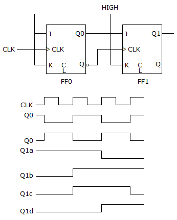
    • 3. The circuit given below has no output on Q1 when examined with an oscilloscope. All J-K inputs are HIGH, the CLK signal is present, and the Q0 is toggling. The C input of FF1 is a constant LOW. What could be causing the problem?


    • Options
    • A. The Q0 output should be connected to the J input of FF1.
    • B. The output of FF0 may be shorted to ground.
    • C. The input of FF1 may be shorted to ground.
    • D. Either the output of FF0 or the input of FF1 may be shorted to ground.
    • Discuss
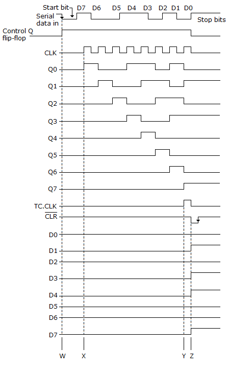
    • 4. Referring to the given figure, what causes the Control FF to reset after D7?


    • Options
    • A. Once the data cycle is initiated by the Start bit, the one-shot produces an output pulse equal to the duration of the eight data bits. Once the eight data bits have been transferred to the data input register, the falling edge of the one-shot pulse resets the Control FF to start the sequence all over again.
    • B. After counting the eight data bits, the divide-by-8 counter produces an output on its active-LOW CLR line to reset the Control FF.
    • C. After counting eight clock pulses equivalent to eight data periods, the terminal count of the divide-by-8 counter and the clock trigger the one-shot, which in turn resets the Control FF and divide-by-8 circuits to begin the sequence all over again. Simultaneously the data is transferred through the output register.
    • D. When the data output register is full, it produces an output on its C terminal that triggers the one-shot, which in turn resets the Control FF.
    • Discuss
    • 5. Which of the following procedures could be used to check the parallel loading feature of a counter?

    • Options
    • A. Preset the LOAD inputs, set the CLR to its active level, and check to see that the Q outputs match the values preset into the LOAD inputs.
    • B. Apply LOWs to the parallel DATA inputs, pulse the CLK input, and check for LOWs on all the Q outputs.
    • C. Apply HIGHs to all the DATA inputs, pulse the CLK and CLR inputs, and check to be sure that the Q outputs are all LOW.
    • D. Apply HIGHs to all the Q terminals, pulse the CLK, and check to see if the DATA terminals now match the Q outputs.
    • Discuss
    • 6. A ripple counter's speed is limited by the propagation delay of:

    • Options
    • A. each flip-flop
    • B. all flip-flops and gates
    • C. the flip-flops only with gates
    • D. only circuit gates
    • Discuss
    • 7. How is an encoder different from a decoder?

    • Options
    • A. The output of an encoder is a binary code for 1-of-N input.
    • B. The output of a decoder is a binary code for 1-of-N input.
    • Discuss
    • 8. Which of the following is not a weighted value positional numbering system:

    • Options
    • A. hexadecimal
    • B. binary-coded decimal
    • C. binary
    • D. octal
    • Discuss
    • 9. What do the mathematical symbols A < b and A > B mean?

    • Options
    • A. A < B means A is greater than B. A > B means A is less than B.
    • B. A > B means A is less than B. A < B means A is greater than B.
    • C. A < B means A is less than B. A > B means A is greater than B.
    • Discuss
    • 10. What is the status of the inputs S0, S1, and S2 of the 74151 eight-line multiplexer in order for the output Y to be a copy of input I5?

    • Options
    • A. S0 = 0, S1 = 1, S2 = 0
    • B. S0 = 0, S1 = 0, S2 = 1
    • C. S0 = 1, S1 = 1, S2 = 0
    • D. S0 = 1, S1 = 0, S2 = 1
    • Discuss


    Comments

    There are no comments.

Enter a new Comment