CuriousTab |
CuriousTab
Discussion
Home ‣ Digital Electronics ‣ Signals and Switches See What Others Are Saying!
- Question
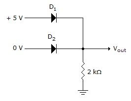
Determine if diodes D1 and D2 in the given figure are forward or reverse biased.
Options- Correct Answer
- D1 forward and D2 reverse
- 6. The simplified form of
 .
.
Options
Discuss
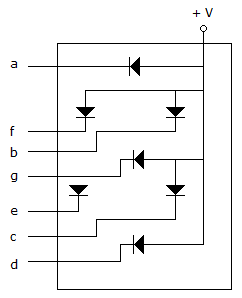
- 9. The diagram given below shows a ________, and in order for the decimal number 3 to be displayed, terminals ________ must be ________.
Options
Discuss
- 10. The device shown in below is a ________ and for the waveforms shown in the accompanying diagram, the ________ output at point X will be ________ and all others will be ________.

Options
Discuss
More questions
Correct Answer: True
Correct Answer: common-anode seven-segment display, abcdg, LOW
Correct Answer: demultiplexer, D3, LOW, HIGH
Comments
There are no comments.