Discussion
Home ‣ Digital Electronics ‣ Digital System Projects Using HDL See What Others Are Saying!
- Question
The frequency counter measures frequency by enabling a counter to count the number of pulses of the incoming waveform during a precisely specified period of time called the sampling time.
Options- A. True
- B. False
- Correct Answer
- False
- 1. A positive edge-triggered flip-flop will accept inputs only when the clock ________.
Options- A. is LOW
- B. changes from HIGH to LOW
- C. is HIGH
- D. changes from LOW to HIGH Discuss
- 2. The high input impedance of MOSFETs:
Options- A. allows faster switching
- B. reduces input current and power dissipation
- C. prevents dense packing
- D. creates low-noise reactions Discuss
- 3. Which of the following is an example of a counter with a truncated modulus?
Options- A. 8
- B. 13
- C. 16
- D. 32 Discuss
- 4. Bidirectional means having two states.
Options- A. True
- B. False Discuss
- 5. The NAND gate is an example of combinational logic.
Options- A. True
- B. False Discuss
- 6. An OR gate with schematic "bubbles" on its inputs performs the same functions as a(n)________ gate.
Options- A. NOR
- B. OR
- C. NOT
- D. NAND Discuss
- 7. The S-R flip-flop has no invalid or unused state.
Options- A. True
- B. False Discuss
- 8. In the digital clock project, when it is 11:59:59, AND gate 1 detects that the tens of hours is 1 and the enable input is active. On the next clock pulse the AM/PM flip-flop will ________.
Options- A. set
- B. reset
- C. toggle
- D. clear Discuss
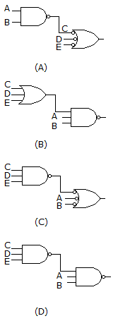
- 9. Implementing the expression
 using NAND logic, we get:
Options- A. (A)
- B. (B)
- C. (C)
- D. (D) Discuss
- 10. One characteristic of a ring counter is that the modulus is equal to the number of flip-flops in the register and, consequently, there are never any unused or invalid states.
Options- A. True
- B. False Discuss
More questions
Correct Answer: changes from LOW to HIGH
Correct Answer: reduces input current and power dissipation
Correct Answer: 13
Correct Answer: False
Correct Answer: True
Correct Answer: NAND
Correct Answer: False
Correct Answer: toggle
Correct Answer: (D)
Correct Answer: False
Comments
There are no comments.More in Digital Electronics:
Programming
Copyright ©CuriousTab. All rights reserved.
