CuriousTab
CuriousTab
Home
Aptitude
Computer
C Programming
C# Programming
C++ Programming
Database
Java Programming
Networking
Engineering
Biochemical Engineering
Biochemistry
Biotechnology
Chemical Engineering
Civil Engineering
Computer Science
Digital Electronics
Electrical Engineering
Electronics
Electronics and Communication Engineering
Mechanical Engineering
Microbiology
Technical Drawing
GK
Current Affairs
General Knowledge
Reasoning
Data Interpretation
Logical Reasoning
Non Verbal Reasoning
Verbal Ability
Verbal Reasoning
Exams
AIEEE
Bank Exams
CAT
GATE
IIT JEE
TOEFL
Jobs
Analyst
Bank Clerk
Bank PO
Database Administrator
IT Trainer
Network Engineer
Project Manager
Software Architect
Discussion
Home
‣
Digital Electronics
‣
Counters
See What Others Are Saying!
Question
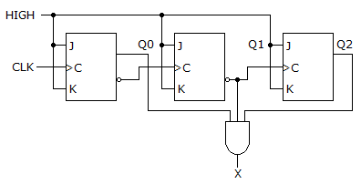
________ is the output frequency of the counter shown below.
Options
A. 4 MHz
B. 20 kHz
C. 210.5 kHz
D. 800 Hz
Correct Answer
20 kHz
More questions
1. The Boolean expression for the logic circuit shown is _____.
Options
A.
B.
C.
D.
Show Answer
Scratch Pad
Discuss
Correct Answer:
2. In the VHDL code of the stepper motor, the
cout
outputs are bit_vector type because they are binary bit patterns.
Options
A. True
B. False
Show Answer
Scratch Pad
Discuss
Correct Answer: True
3. The term
race condition
describes the time that an active signal must be present at the input to a flip-flop before an active clock edge is applied.
Options
A. True
B. False
Show Answer
Scratch Pad
Discuss
Correct Answer: False
4. A method for the automated testing of printed circuit boards is called a(n) ________.
Options
A. bed-of-nails
B. LUT
C. CLB
D. CPLD
Show Answer
Scratch Pad
Discuss
Correct Answer: bed-of-nails
5. Which of the following logic families has the shortest propagation delay?
Options
A. CMOS
B. BiCMOS
C. ECL
D. 74SXX
Show Answer
Scratch Pad
Discuss
Correct Answer: ECL
6. What is the input/output pin configuration of the GAL22V10?
Options
A. 10 output pins and 12 input pins
B. 2 special-purpose pins
C. 8 pins that are either inputs or outputs
D. All of the above
Show Answer
Scratch Pad
Discuss
Correct Answer: 10 output pins and 12 input pins
7. List the state of each output pin of a 7447 if
RBI
= 0,
LT
= 1,
A
0
= 1,
A
1
= 0,
A
2
= 0, and
A
3
= 1.
Options
A.
RBO
= 0,
a
= 0,
b
= 0,
c
= 0,
d
= 1,
e
= 1,
f
= 0,
g
= 0
B.
RBO
= 1,
a
= 0,
b
= 0,
c
= 0,
d
= 1,
e
= 1,
f
= 0,
g
= 0
C.
RBO
= 0,
a
= 0,
b
= 0,
c
= 0,
d
= 0,
e
= 1,
f
= 0,
g
= 0
D.
RBO
= 1,
a
= 0,
b
= 0,
c
= 0,
d
= 0,
e
= 1,
f
= 0,
g
= 0
Show Answer
Scratch Pad
Discuss
Correct Answer:
RBO
= 0,
a
= 0,
b
= 0,
c
= 0,
d
= 1,
e
= 1,
f
= 0,
g
= 0
8. Which statement below best describes the function of a decoder?
Options
A. A decoder will convert a decimal number into the proper binary equivalent.
B. A decoder will convert a binary number into a specific output representing a particular character or digit.
C. Decoders are used to prevent improper operation of digital systems.
D. Decoders are special ICs that are used to make it possible for one brand of computer to talk to another.
Show Answer
Scratch Pad
Discuss
Correct Answer: A decoder will convert a binary number into a specific output representing a particular character or digit.
9. Convert the following SOP expression to an equivalent POS expression.
Options
A.
B.
C.
D.
Show Answer
Scratch Pad
Discuss
Correct Answer:
10. What is the difference between the 74HC00 series and the 74HCT00 series of CMOS logic?
Options
A. The HCT series is faster.
B. The HCT series is slower.
C. The HCT series is input and output voltage compatible with TTL.
D. The HCT series is not input and output voltage compatible with TTL.
Show Answer
Scratch Pad
Discuss
Correct Answer: The HCT series is input and output voltage compatible with TTL.
Comments
There are no comments.
Enter a new Comment
Save
More in Digital Electronics:
Boolean Algebra and Logic Simplification
Code Converters and Multiplexers
Combinational Logic Analysis
Combinational Logic Circuits
Computers
Counters
Describing Logic Circuits
Digital Arithmetic Operations and Circuits
Digital Concepts
Digital Design
Digital Signal Processing
Digital System Projects Using HDL
Ex-OR and Ex-NOR Gates
Flip-Flops
Integrated-Circuit Logic Families
Integrated Circuit Technologies
Interfacing to the Analog World
Logic Families and Their Characteristics
Logic Gates
Memory and Storage
Microprocessor Fundamentals
MSI Logic Circuits
Multivibrators and 555 Timer
Number Systems and Codes
Programmable Logic Device
Shift Registers
Signals and Switches
The 8051 Microcontroller