Discussion
Home ‣ Digital Electronics ‣ Describing Logic Circuits See What Others Are Saying!
- Question
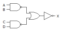
The figure given below is an example of the implementation of AND-OR-INVERT logic.

Options- A. True
- B. False
- Correct Answer
- False
- 1. The concurrent section of the hardware description is where the ________ are interconnected.
Options- A. functions
- B. components
- C. circuits
- D. macrofunctions Discuss
- 2. Output 6 of a 74138 octal decoder is selected when it is enabled by a data input of:
A0 = 1
A1 = 1
A2 = 0
Options- A. True
- B. False Discuss
- 3. Assume a ROM to be tested is compared with a known good ROM. If the checksums differ, the ROM is ________.
Options- A. very likely to be good
- B. definitely good
- C. very likely to be bad
- D. definitely bad Discuss
- 4. The most common TTL series ICs are:
Options- A. E-MOSFET
- B. 7400
- C. quad
- D. AC00 Discuss
- 5. Microcontrollers often have:
Options- A. CPUs
- B. RAM
- C. ROM
- D. all of the above Discuss
- 6. Before an SOP implementation, the expression
 would require a total of how many gates?
Options- A. 1
- B. 2
- C. 4
- D. 5 Discuss
- 7. The outputs of a 7485 four-bit magnitude comparator when the inputs are A = 0110 and B = 1010 are:
A < B is 1
A = B is 0
A > B is 1
Options- A. True
- B. False Discuss
- 8. How many outputs are on a BCD decoder?
Options- A. 4
- B. 16
- C. 8
- D. 10 Discuss
- 9. The GAL16V8 has eight dedicated input pins.
Options- A. True
- B. False Discuss
- 10. The Boolean expression AB + CD is an example of ________.
Options- A. PAL
- B. GAL
- C. SOP
- D. POS Discuss
More questions
Correct Answer: components
Correct Answer: False
Correct Answer: definitely bad
Correct Answer: 7400
Correct Answer: all of the above
Correct Answer: 5
Correct Answer: False
Correct Answer: 10
Correct Answer: True
Correct Answer: SOP
Comments
There are no comments.More in Digital Electronics:
Programming
Copyright ©CuriousTab. All rights reserved.
