CuriousTab |
CuriousTab
Discussion
Home ‣ Digital Electronics ‣ Logic Gates See What Others Are Saying!
- Question
The gates in this figure are implemented using TTL logic. If the input of the inverter is open, and you apply logic pulses to point B, the output of the AND gate will be ________.
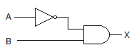
Options- Correct Answer
- a steady LOW
- 1. The systems shown in the given figure communicate using ________.
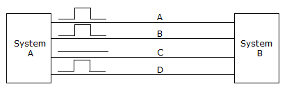
Options
Discuss
- 8. All outputs of the 74138 octal decoder are disabled (HIGH) when the enable inputs are:
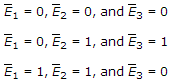
Options
Discuss
- 10. The designation
 means that the ________.
Options
Discuss
More questions
Correct Answer: parallel data
Correct Answer: True
Correct Answer: up count is active-HIGH, the down count is active-LOW
Comments
There are no comments.