Discussion
Home ‣ Digital Electronics ‣ Integrated-Circuit Logic Families See What Others Are Saying!
- Question
What type of circuit is shown below, and how is the output ordinarily connected?
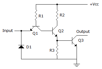
Options- A. It is an open-collector gate and is used to drive loads that cannot be connected directly to Vcc due to high noise levels.
- B. It represents an active-LOW inverter and is used in negative logic systems.
- C. It is an open-collector gate. An external load must be connected between the output terminal and an appropriate supply voltage.
- D. Any of the above could be correct, depending on the specific application involved.
- Correct Answer
- It is an open-collector gate. An external load must be connected between the output terminal and an appropriate supply voltage.
- 1. PALs tend to execute ________ logic.
Options- A. SAP
- B. SOP
- C. PLA
- D. SPD Discuss
- 2. 34FC + AD31 = ________.
Options- A. E22D
- B. E31D
- C. E21D
- D. E42D Discuss
- 3. A decimal 11 in BCD is ________.
Options- A. 00001011
- B. 00001100
- C. 00010001
- D. 00010010 Discuss
- 4. Convert the following BCD number to decimal.
010101101001bcd
Options- A. 539
- B. 2551
- C. 569
- D. 1552 Discuss
- 5. Parallel transmission is faster than serial.
Options- A. True
- B. False Discuss
- 6. The complement of 1 is 0.
Options- A. True
- B. False Discuss
- 7. Digital signal processing must be at least half as fast as the incoming signal to be processed.
Options- A. True
- B. False Discuss
- 8. In the keypad HDL encoder, NANDing of the columns is used to activate the freeze bit.
Options- A. True
- B. False Discuss
- 9. Resolution in the analog output of a DAC is primarily dependent on the number of input binary bits.
Options- A. True
- B. False Discuss
- 10. The carry-out of a binary adder is identified using the summation symbol, sigma.
Options- A. True
- B. False Discuss
More questions
Correct Answer: SOP
Correct Answer: E22D
Correct Answer: 00010001
Correct Answer: 569
Correct Answer: True
Correct Answer: True
Correct Answer: False
Correct Answer: False
Correct Answer: True
Correct Answer: False
Comments
There are no comments.More in Digital Electronics:
Programming
Copyright ©CuriousTab. All rights reserved.