Discussion
Home ‣ Digital Electronics ‣ Counters See What Others Are Saying!
- Question
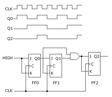
A four-channel scope is used to check the counter in the figure given below. Are the displayed waveforms correct?

Options- A. Yes
- B. No
- Correct Answer
- No
- 1. A retriggerable one-shot has a pulse width of 10 ms; 3 ms after being triggered, another trigger pulse is applied. The resulting output pulse will be ________ mS.
Options- A. 3
- B. 7
- C. 10
- D. 13 Discuss
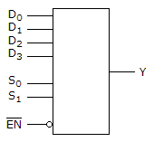
- 2. The device shown here is most likely a ________.

Options- A. comparator
- B. multiplexer
- C. demultiplexer
- D. parity generator Discuss
- 3. The symbol shown below is for a 2-input NAND gate.

Options- A. True
- B. False Discuss
- 4. In HDL, one of the strategies used in strategic planning is to find a way to test each piece of the project.
Options- A. True
- B. False Discuss
- 5. A D latch has one data-input line.
Options- A. True
- B. False Discuss
- 6. Decimal 474 is ________ in BCD.
Options- A. 0100 0111 0100
- B. 0100 1011 0101
- C. 0100 1001 0011
- D. 0110 1011 1001 Discuss
- 7. Each hexadecimal digit converts to ________ binary digits.
Options- A. four
- B. eight
- C. 12
- D. six Discuss
- 8. Determine the values of A, B, C, and D that make the product term
 equal to 1.
Options- A. A = 0, B = 1, C = 0, D = 1
- B. A = 0, B = 0, C = 0, D = 1
- C. A = 1, B = 1, C = 1, D = 1
- D. A = 0, B = 0, C = 1, D = 0 Discuss
- 9. Another name for a multiplexer is ________.
Options- A. encoder
- B. decoder
- C. code converter
- D. data selector Discuss
- 10. All decade counters are BCD counters.
Options- A. True
- B. False Discuss
More questions
Correct Answer: 13
Correct Answer: multiplexer
Correct Answer: False
Correct Answer: True
Correct Answer: True
Correct Answer: 0100 0111 0100
Correct Answer: four
Correct Answer: A = 0, B = 1, C = 0, D = 1
Correct Answer: data selector
Correct Answer: False
Comments
There are no comments.More in Digital Electronics:
Programming
Copyright ©CuriousTab. All rights reserved.
