CuriousTab |
CuriousTab
Discussion
Home ‣ Digital Electronics ‣ Describing Logic Circuits Comments
- Question
Which of the figures given below represents a NAND gate?
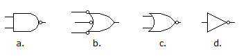
Options- Correct Answer
- a
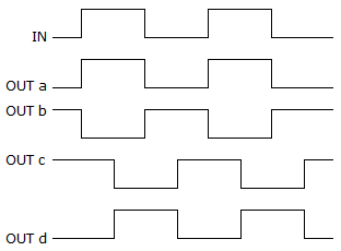
- 1. Which timing diagram shown below is correct for an inverter?
Options
Discuss
- 2. Simplify the expression
 using DeMorgan's theorems.
Options- A.

- B.

- C.

- D.
 Discuss
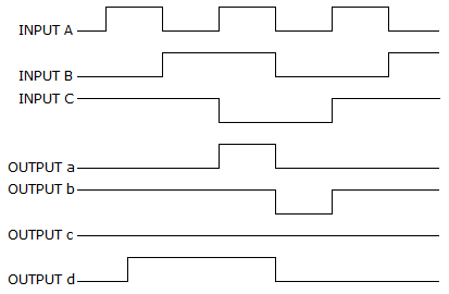
- 3. For a 3-input NAND gate, with the input waveforms as shown below, which output waveform is correct?

Options
Discuss
- 4. Which of the figures given below represents a NOR gate?
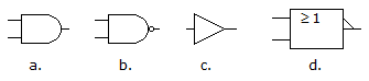
Options
Discuss
- 5. For a three-input OR gate, with the input waveforms as shown below, which output waveform is correct?
Options
Discuss
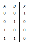
- 6. Which logic gate does this truth table describe?
Options
Discuss
Describing Logic Circuits problems
Search Results
Correct Answer: b
Correct Answer:
Correct Answer: c
Correct Answer: d
Correct Answer: b
Correct Answer: NOR
Comments
There are no comments.