CuriousTab
Search
CuriousTab
Home
Aptitude
Computer
C Programming
C# Programming
C++ Programming
Database
Java Programming
Networking
Engineering
Biochemical Engineering
Biochemistry
Biotechnology
Chemical Engineering
Civil Engineering
Computer Science
Digital Electronics
Electrical Engineering
Electronics
Electronics and Communication Engineering
Mechanical Engineering
Microbiology
Technical Drawing
GK
Current Affairs
General Knowledge
Reasoning
Data Interpretation
Logical Reasoning
Non Verbal Reasoning
Verbal Ability
Verbal Reasoning
Exams
AIEEE
Bank Exams
CAT
GATE
IIT JEE
TOEFL
Jobs
Analyst
Bank PO
Database Administrator
IT Trainer
Network Engineer
Project Manager
Software Architect
Discussion
Home
‣
Digital Electronics
‣
Multivibrators and 555 Timer
Comments
Question
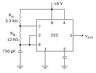
Determine
t
HI
and
t
LO
for the circuit given below.
Options
A.
t
HI
= 7.95 µs,
t
LO
= 6.24 µs
B.
t
HI
= 6.24 µs,
t
LO
= 7.95 µs
C.
t
HI
= 3.97 µs,
t
LO
= 3.21 µs
D.
t
HI
= 3.21 µs,
t
LO
= 3.97 µs
Correct Answer
t
HI
= 7.95 µs,
t
LO
= 6.24 µs
Multivibrators and 555 Timer problems
Search Results
1. Is there any limit to the number of times that a 74123 can be retriggered?
Options
A. yes
B. no
Show Answer
Scratch Pad
Discuss
Correct Answer: no
2. A crystal demonstrates the ________ effect when a mechanical force across the crystal causes a small voltage to be generated.
Options
A. photoelectric
B. Co-pitts
C. piezoelectric
D. flywheel
Show Answer
Scratch Pad
Discuss
Correct Answer: piezoelectric
3. An astable multivibrator requires:
Options
A. balanced time constants
B. a pair of matched transistors
C. no input signal
D. dual
J
-
K
flip-flops
Show Answer
Scratch Pad
Discuss
Correct Answer: no input signal
4. To obtain a 50% duty cycle in an astable 555 timer circuit:
Options
A.
t
LO
=
t
HI
B.
R
A
=
R
B
and short
R
B
with a diode during the capacitor charging cycle
C. capacitor voltage must rise above 1/3
V
CC
D.
t
LO
=
t
HI
,
R
A
=
R
B
, and short
R
B
with a diode during the capacitor charging cycle
Show Answer
Scratch Pad
Discuss
Correct Answer:
t
LO
=
t
HI
5. If a diode is connected across resistor
R
B
(positive end up) in the given figure, what is the new duty cycle of the output waveform?
Options
A. 56%
B. 44%
C. 21.6%
D. 17.4%
Show Answer
Scratch Pad
Discuss
Correct Answer: 21.6%
6. An astable 555 timer has the following number of stable states:
Options
A. 0
B. 1
C. 2
D. 3
Show Answer
Scratch Pad
Discuss
Correct Answer: 0
7. What is the output pulse width of the waveform at the output of the circuit in the given figure?
Options
A. 1.65 ms
B. 18.2 ms
C. 4.98 ms
D. 54.6 ms
Show Answer
Scratch Pad
Discuss
Correct Answer: 18.2 ms
8. What is the difference between an astable multivibrator and a monostable multivibrator?
Options
A. The astable is free running.
B. The astable needs to be clocked.
C. The monostable is free running.
D. none of the above
Show Answer
Scratch Pad
Discuss
Correct Answer: The astable is free running.
9. A retriggerable one shot has a pulse of 10 ms. 3 ms after being triggered, another trigger pulse is applied. The resulting output pulse will be ________ ms.
Options
A. 3
B. 7
C. 10
D. 13
Show Answer
Scratch Pad
Discuss
Correct Answer: 13
10. Which mode of operation is being used when a 555 timer chip has two external resistors and an external capacitor?
Options
A. monostable
B. pulse stretching
C. Schmitt triggering
D. astable
Show Answer
Scratch Pad
Discuss
Correct Answer: astable
Comments
There are no comments.
Enter a new Comment
Save
More in Digital Electronics:
Boolean Algebra and Logic Simplification
Code Converters and Multiplexers
Combinational Logic Analysis
Combinational Logic Circuits
Computers
Counters
Describing Logic Circuits
Digital Arithmetic Operations and Circuits
Digital Concepts
Digital Design
Digital Signal Processing
Digital System Projects Using HDL
Ex-OR and Ex-NOR Gates
Flip-Flops
Integrated-Circuit Logic Families
Integrated Circuit Technologies
Interfacing to the Analog World
Logic Families and Their Characteristics
Logic Gates
Memory and Storage
Microprocessor Fundamentals
MSI Logic Circuits
Multivibrators and 555 Timer
Number Systems and Codes
Programmable Logic Device
Shift Registers
Signals and Switches
The 8051 Microcontroller