CuriousTab |
CuriousTab
Discussion
Home ‣ Digital Electronics ‣ MSI Logic Circuits See What Others Are Saying!
- Question
It is suspected that the comparator in the figure given below has a problem. The inputs are activated in the table shown below and the corresponding outputs noted. What is most likely wrong with the circuit?
For P0 ? P3 = 1 and Q0 ? Q3 = 0, P > Q = 1, P = Q = 1, P < Q = 0
For P0 ? P3 = 0 and Q0 ? Q3 = 1, P > Q = 0, P = Q = 1, P < Q = 1
For P0 ? P3 = 1 and Q0 ? Q3 = 1, P > Q = 0, P = Q = 1, P < Q = 0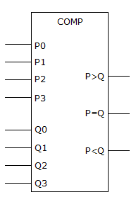
Options- Correct Answer
- The P = Q output is shorted to Vcc.
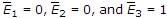
- 9. The outputs of the 74138 octal decoder are enabled when the enable inputs are
 .
.
Options
Discuss
More questions
Correct Answer: True
Comments
There are no comments.