CuriousTab |
CuriousTab
Discussion
Home ‣ Digital Electronics ‣ Digital Arithmetic Operations and Circuits See What Others Are Saying!
- Question
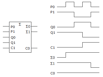
What is wrong, if anything, with the circuit in the given figure based on the logic analyzer display accompanying the circuit?
Options- Correct Answer
- The P1 input is not being added into the total.
- 6. In a negative logic system, the area represented by #3 in the given figure would be the ________ level.

Options
Discuss
More questions
Correct Answer: HIGH
Comments
There are no comments.