CuriousTab |
CuriousTab
Analog Electronics problems
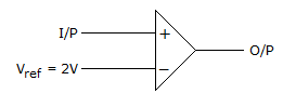
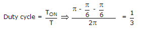
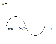
- 1. If the input to the ideal comparator shown in the figure is a sinusoidal signal of 8 V (peak to peak) without any DC component, then the output of the comparator has a duty cycle of
Options
Discuss
Correct Answer: 1/3
Explanation:
Options
Discuss
Correct Answer: 360°
Explanation:
Gain of system with + ve feedback = 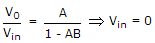 for oscillation
for oscillation
but V0 ? 0
so, that 1 - AB = 0 ⟹ AB = 1 ?0° or 360°.
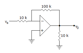
- 3. The input impedance of op-amp circuit of figure is
Options
Discuss
Correct Answer: 10 k ohm
Explanation:
Due to the presence of virtual ground at input, the resistance in the series path of input of inverting amplifier is input impedance.
 .
.
 .
.
 .
.