Discussion
Home ‣ Electronics ‣ RC Circuits See What Others Are Saying!
- Question

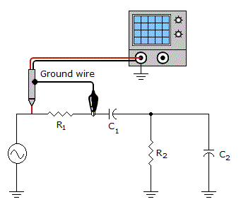
Connecting the oscilloscope as shown in the given figure will _____.
Options- A. measure the voltage across the source
- B. measure the voltage across C1, R2, and C2
- C. short R1
- D. short C1, R2, and C2
- Correct Answer
- short C1, R2, and C2
- 1. A ______ is not a multivibrator.
Options- A. one-shot
- B. flip-flop
- C. VCO
- D. bistable Discuss
- 2. Inductors are not as versatile as capacitors.
Options- A. True
- B. False Discuss
- 3. In the gray code, each number is 3 greater than the binary representation of that number.
Options- A. True
- B. False Discuss
- 4. Between any two time constants, the charge on a capacitor changes about 63%.
Options- A. True
- B. False Discuss
- 5. An inductor will boost current flow.
Options- A. True
- B. False Discuss
- 6. ___ capacitors have the highest values of capacitance.
Options- A. Electrolytic
- B. Ceramic
- C. Plastic-film
- D. Mica Discuss
- 7. A series circuit provides only one path for current between two points.
Options- A. True
- B. False Discuss
- 8. What is the ratio of 13 to 47 expressed in percent?
Options- A. 2.76%
- B. 27.7%
- C. 3.60%
- D. 36.1% Discuss
- 9. What is the permeability of transformer iron?
Options- A. 50
- B. 450
- C. 1,500
- D. 5,500 Discuss
- 10. The voltages across all components in parallel are equal.
Options- A. True
- B. False Discuss
More questions
Correct Answer: one-shot
Correct Answer: True
Correct Answer: False
Correct Answer: True
Correct Answer: False
Correct Answer: Electrolytic
Correct Answer: True
Correct Answer: 27.7%
Correct Answer: 5,500
Correct Answer: True
Comments
There are no comments.More in Electronics:
Programming
Copyright ©CuriousTab. All rights reserved.
