Discussion
Home ‣ Electronics ‣ RL Circuits See What Others Are Saying!
- Question

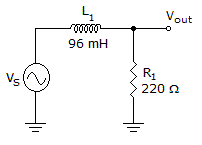
The cutoff frequency of the circuit in the given circuit is approximately equal to _____.
Options- A. 21 Hz
- B. 60 Hz
- C. 0 Hz
- D. 365 Hz
- Correct Answer
- 365 Hz
- 1. Clampers are often called peak detectors.
Options- A. True
- B. False Discuss
- 2. A transformer that has 700 turns in the primary and 35 turns in the secondary has a turns ratio of 20:1.
Options- A. True
- B. False Discuss
- 3. The operands in an addition operation consist of the augend and the addend.
Options- A. True
- B. False Discuss
- 4. In a BJT, the collector current is approximately equal to the base current.
Options- A. True
- B. False Discuss
- 5. A sine wave has:
Options- A. four quadrants
- B. two alternations
- C. one period
- D. all of the above Discuss
- 6. The greater the selectivity, the wider the bandwidth.
Options- A. True
- B. False Discuss
- 7. The unit of magnetic flux density is the weber.
Options- A. True
- B. False Discuss
- 8. PROMs are volatile.
Options- A. True
- B. False Discuss
- 9. A monostable multivibrator must be triggered.
Options- A. True
- B. False Discuss
- 10. Generally, increasing the resistance in a circuit will decrease the current.
Options- A. True
- B. False Discuss
More questions
Correct Answer: False
Correct Answer: True
Correct Answer: True
Correct Answer: False
Correct Answer: all of the above
Correct Answer: False
Correct Answer: False
Correct Answer: False
Correct Answer: True
Correct Answer: True
Comments
There are no comments.More in Electronics:
Programming
Copyright ©CuriousTab. All rights reserved.
