Discussion
Home ‣ Electronics ‣ RLC Circuits and Resonance See What Others Are Saying!
- Question

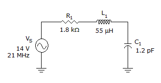
The voltage across the inductor is ______ in the given circuit.
Options- A. 6.5 V
- B. 12.4 V
- C. 14 V
- D. 50 V
- Correct Answer
- 50 V
- 1. What procedure should be followed when troubleshooting with an ammeter or voltmeter?
Options- A. Short the leads and adjust.
- B. Check the meter's external power supply.
- C. Start with the highest scale and adjust down to a lower scale.
- D. Start with the lowest scale and adjust up to a higher scale. Discuss
- 2. Voltage-divider bias provides:
Options- A. an unstable Q point
- B. a stable Q point
- C. a Q point that easily varies with changes in the transistor's current gain
- D. a Q point that is stable and easily varies with changes in the transistor's current gain Discuss
- 3. Kirchhoff's voltage law states that:
Options- A. the sum of the voltage drops in a series circuit is equal to the total applied voltage
- B. the algebraic sum of the resistances is equal to the sum of the voltages
- C. the algebraic sum of the individual currents around a closed loop is zero
- D. the voltages developed across each element in a series circuit are identical Discuss
- 4. Clampers are often called peak detectors.
Options- A. True
- B. False Discuss
- 5. A transformer that has 700 turns in the primary and 35 turns in the secondary has a turns ratio of 20:1.
Options- A. True
- B. False Discuss
- 6. The operands in an addition operation consist of the augend and the addend.
Options- A. True
- B. False Discuss
- 7. In a BJT, the collector current is approximately equal to the base current.
Options- A. True
- B. False Discuss
- 8. A sine wave has:
Options- A. four quadrants
- B. two alternations
- C. one period
- D. all of the above Discuss
- 9. The greater the selectivity, the wider the bandwidth.
Options- A. True
- B. False Discuss
- 10. The unit of magnetic flux density is the weber.
Options- A. True
- B. False Discuss
More questions
Correct Answer: Start with the highest scale and adjust down to a lower scale.
Correct Answer: a stable Q point
Correct Answer: the sum of the voltage drops in a series circuit is equal to the total applied voltage
Correct Answer: False
Correct Answer: True
Correct Answer: True
Correct Answer: False
Correct Answer: all of the above
Correct Answer: False
Correct Answer: False
Comments
There are no comments.More in Electronics:
Programming
Copyright ©CuriousTab. All rights reserved.
