Discussion
Home ‣ Electronics ‣ Combinational Logic Circuits See What Others Are Saying!
- Question
A circuit that responds to a specific set of signals to produce a related digital signal output is called a(n):
Options- A. BCD matrix
- B. display driver
- C. encoder
- D. decoder
- Correct Answer
- encoder
- 1.

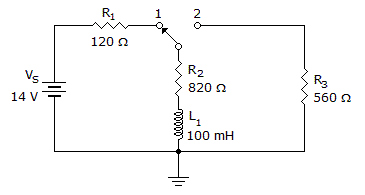
In the given circuit, what will the voltage be across R3 25 µs after the switch is moved to position 2?
Options- A. 2.88 V
- B. 5.9 V
- C. 8.34 V
- D. 14 V Discuss
- 2.

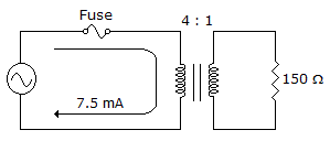
The reflected resistance is ___ as seen by the source in the given circu.
Options- A. 150 Ω
- B. 300 Ω
- C. 600 Ω
- D. 2.4 kΩ Discuss
- 3. The unit designator for resistance value is the:
Options- A. ampere
- B. ohm
- C. volt
- D. watt Discuss
- 4. A(n) ___ has a conductive channel only when it is biased properly.
Options- A. p-channel JFET
- B. n-channel D-MOSFET
- C. p-channel D-MOSFET
- D. n-channel E-MOSFET Discuss
- 5. The difference between analog voltage represented by two adjacent digital codes, or the analog step size, is the:
Options- A. quantization
- B. accuracy
- C. resolution
- D. monotonicity Discuss
- 6. A "U" shaped, opposite-polarity material built near a JFET-channel center is called the:
Options- A. gate
- B. block
- C. drain
- D. heat sink Discuss
- 7. Which test equipment best allows a comparison between input and output signals?
Options- A. an oscilloscope
- B. a logic probe
- C. a spectrum analyzer
- D. a multitrace oscilloscope Discuss
- 8. When multiplying in binary the decimal values 13 × 11, what is the third partial product?
Options- A. 100000
- B. 100001
- C. 0000
- D. 1011 Discuss
- 9. A voltage-follower op-amp has the output connected directly to the inverting input.
Options- A. True
- B. False Discuss
- 10.

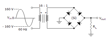
The average value of the output voltage from the circuit in the given circuit equals ___.
Options- A. 5.48 V
- B. 2.74 V
- C. 0 V
- D. 6.37 V Discuss
More questions
Correct Answer: 5.9 V
Correct Answer: 2.4 kΩ
Correct Answer: ohm
Correct Answer: n-channel E-MOSFET
Correct Answer: resolution
Correct Answer: gate
Correct Answer: a multitrace oscilloscope
Correct Answer: 100000
Correct Answer: True
Correct Answer: 5.48 V
Comments
There are no comments.More in Electronics:
Programming
Copyright ©CuriousTab. All rights reserved.
