Digital Electronics problems
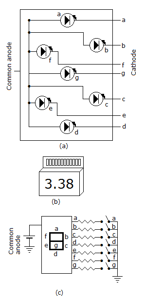
- 1. A device which converts BCD to seven segment is called
Options- A. encoder
- B. decoder
- C. multiplexer
- D. none of these Discuss
Correct Answer: decoder
Explanation:
Decoder converts binary/BCD to alphanumeric.
- 2. A 12 bit ADC is used to convert analog voltage of 0 to 10 V into digital. The resolution is
Options- A. 2.44 mV
- B. 24.4 mV
- C. 1.2 V
- D. none of the above Discuss
Correct Answer: 2.44 mV
Explanation:
 .
.
- 3. In a 7 segment display, LEDs b and c lit up. The decimal number displayed is
Options- A. 9
- B. 7
- C. 3
- D. 1 Discuss
Correct Answer: 1
Explanation:

- 4. BCD input 1000 is fed to a 7 segment display through a BCD to 7 segment decoder/driver. The segments which will lit up are
Options- A. a, b, d
- B. a, b, c
- C. all
- D. a, b, g, c, d Discuss
Correct Answer: all
Explanation:
1000 equals decimal 8 Therefore all segments will lit up.
- 5. 7BF16 = __________ 2
Options- A. 0111 1011 1110
- B. 0111 1011 1111
- C. 0111 1011 0111
- D. 0111 1011 0011 Discuss
Correct Answer: 0111 1011 1111
Explanation:
7BF16 = 7 x 162 + 11 x 161 + 15 x 160 = 1983 in decimal = 0111 1011 1111 in binary.
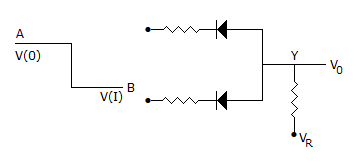
- 6. The circuit in the given figure is

Options- A. positive logic OR gate
- B. negative logic OR gate
- C. negative logic AND gate
- D. positive logic AND gate Discuss
Correct Answer: negative logic OR gate
Explanation:
Since V(1) is lower state than V(0) it is a negative logic circuit. Since diodes are in parallel, it is an OR gate.
- 7. In a BCD to 7 segment decoder the minimum and maximum number of outputs active at any time is
Options- A. 2 and 7
- B. 3 and 7
- C. 1 and 6
- D. 3 and 6 Discuss
Correct Answer: 2 and 7
Explanation:
Minimum number of outputs when input is decimal 1 and maximum number of outputs when input is decimal 8.
- 8. For the gate in the given figure the output will be

Options- A. 0
- B. 1
- C. A
- D. A Discuss
Correct Answer: A
Explanation:
If A = 0, Y = 1 and A = 1, Y = 0 Therefore Y = A.
- 9. AB + AB =
Options- A. B
- B. A
- C. 1
- D. 0 Discuss
Correct Answer: A
Explanation:
AB + AB = A(B + B) = A . 1 = A.
- 10. A three state switch has three outputs. These are
Options- A. low, low and high
- B. low, high, high
- C. low. floating, low
- D. low, high, floating Discuss
Correct Answer: low, high, floating
Explanation:
Third state is floating.
More in Electronics and Communication Engineering:
Programming
Copyright ©CuriousTab. All rights reserved.
