Discussion
Home ‣ Electrical Engineering ‣ RL Circuits See What Others Are Saying!
- Question
In an RL circuit, the impedance is determined by both the resistance and the inductive reactance combined.
Options- A. True
- B. False
- Correct Answer
- True
- 1. When the current through a 12 kΩ resistor is 8 mA, the power is
Options- A. 7.68 mW
- B. 768 mW
- C. 7.68 W
- D. 76.8 W Discuss
- 2. In an RL circuit, part of the power is resistive and part is reactive.
Options- A. True
- B. False Discuss
- 3. The inductance of an iron-core coil decreases if
Options- A. the number of turns is decreased
- B. the iron core is removed
- C. the length of the coil decreases
- D. none of the above Discuss
- 4. A transformer with a 110 V primary has a 15:1 turns ratio. The load resistance, RL, is 120 Ω. What is the approximate voltage across the load?
Options- A. 7.3 V
- B. 73 V
- C. 88 V
- D. 880 V Discuss
- 5. A 220 Ω resistor is in series with a 2.2 µF capacitor. The time constant is
Options- A. 48 µs
- B. 480 µs
- C. 2.42 µs
- D. 24 µs Discuss
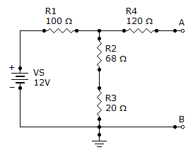
- 6. Find the Thevenin equivalent (VTH and RTH) between terminals A and B of the circuit given.

Options- A. 562 mV, 167 Ω
- B. 5.62 V, 167 Ω
- C. 5.62 V, 188 Ω
- D. 562 mV, 188 Ω Discuss
- 7. Referring to Problem 15, if the input voltage is a 6 V sine wave with a dc level of 10 V, what is the output voltage magnitude?
Options- A. 6 V
- B. 597 mV
- C. 5.97 V
- D. 0 V Discuss
- 8. The minimum resistance value for a blue, gray, red, silver resistor is
Options- A. 612 Ω
- B. 6,120 Ω
- C. 6,800 Ω
- D. 6,460 Ω Discuss
- 9. Four 8 Ω speakers are connected in parallel to the output of an audio amplifier. If the maximum voltage to the speakers is 12 V, the amplifier must be able to deliver to the speakers
Options- A. 18 W
- B. 1.5 W
- C. 48 W
- D. 72 W Discuss
- 10. Referring to circuit given, if R1 is changed to a 68 Ω resistor, what will be the current through it?

Options- A. 0.16 A
- B. 0.24 A
- C. 0.2 A
- D. 0.04 A Discuss
More questions
Correct Answer: 768 mW
Correct Answer: True
Correct Answer: the number of turns is decreased
Correct Answer: 7.3 V
Correct Answer: 480 µs
Correct Answer: 5.62 V, 167 Ω
Correct Answer: 5.97 V
Correct Answer: 6,120 Ω
Explanation:
Because of 10% tolerance(last color silver), this resistance may vary 10% of 6800.
Minimum resistance value = 6800 - 680 = 6120
Maximum resistance value = 6800 + 680 = 7480
Correct Answer: 72 W
Correct Answer: 0.16 A
Comments
There are no comments.More in Electrical Engineering:
Programming
Copyright ©CuriousTab. All rights reserved.
