CuriousTab |
CuriousTab
Discussion
Home ‣ Electronics and Communication Engineering ‣ Microwave Communication See What Others Are Saying!
- Question
Options- Correct Answer
- converts velocity modulation into current modulation of beam
ExplanationA Klystron is a vacuum tube used for generation/amplification of microwaves.An electron beam is produced by oxide coated indirectly heated cathode and is focussed and accelerated by focussing electrode.
This beam is transmitted through a glass tube. The input cavity where the beam enters the glass tube is called buncher.
As electrons move ahead they see an accelerating field for half cycle and retarding field for the other half cycle.
Therefore, some electrons are accelerated and some are retarded. This process is called velocity modulation.
The velocity modulation causes bunching of electrons. This bunching effect converts velocity modulation into density modulation of beam.
The input is fed at buncher cavity and output is taken at catcher cavity.
In a two cavity klystron only buncher and catcher cavity are used. In multi cavity klystron one or more intermediate cavities are also used.
The features of a multicavity klystron are :
1. Frequency range - 0.25 GHz to 100 GHz
2. Power output - 10 kW to several hundred kW
3. Power gain - 60 dB (nominal value)
4. Efficiency - about 40%.
A multicavity klystron is used in UHF TV transmitters, Radar transmitter and satellite communication.
More questions
- 3. Consider the common emitter amplifier shown below with the following circuit parameters: ? = 100, gm = 0.3861 A/V, r0 = ? rp = 259 ?, Rs = 1 k?, RB = 93 k?, RC = 250 ?, RL = 1 kW, C1 = ? and C2 = 4.7mF.
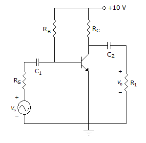
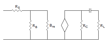
The resistance seen by the source Vs is
Options
Discuss
Correct Answer: 1258 ?
Explanation:
Zs = Rs + (RB || Brs)rc = 2.475 = 1.258 kV
Options- A.
- B.
- C.
- D.
 Discuss
Correct Answer:
Options- D.
 Discuss
Correct Answer: (n - 1) A
Explanation:
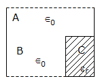
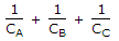
If the number of plates is n, the number of capacitors is (n - 1).- 10. Figure shows a composite capacitor. If CA, CB, CC are the capacitances of capacitors A, B, C, the overall capacitance C is
Options- C. C =

- D. C =
 Discuss
Correct Answer: C =
Explanation:
B and C are in series and A is in parallel with this combination.
Comments
There are no comments.
- 3. Consider the common emitter amplifier shown below with the following circuit parameters: ? = 100, gm = 0.3861 A/V, r0 = ? rp = 259 ?, Rs = 1 k?, RB = 93 k?, RC = 250 ?, RL = 1 kW, C1 = ? and C2 = 4.7mF.