Discussion
Home ‣ Electronics and Communication Engineering ‣ Microwave Communication See What Others Are Saying!
- Question
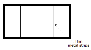
In mode filter of the given figure which of the following modes is unaffected

Options- A. TE01
- B. TE10
- C. TE11
- D. all TM
- Correct Answer
- TE01
ExplanationTE01 mode is unaffected because its horizontally oriented electric field is every where perpendicular to the conducting strips.
More questions
- 1. Radar reciever has high sensitivity and low noise figure
Options- A. True
- B. False Discuss
Correct Answer: True
- 2. A single phase electric heater uses phase controlled thyristors. The firing angle is 90°. The degree of heating is
Options- A. 25% of maximum
- B. 50% of maximum
- C. 75% of maximum
- D. none of the above Discuss
Correct Answer: 50% of maximum
Explanation:
Conduction occurs only during 50% of wave.- 3. A characteristic property of crystal is its periodicity of structure.
Options- A. True
- B. False Discuss
Correct Answer: True
- 4. The number of distinct Boolean expression of 4 variables is
Options- A. 16
- B. 256
- C. 1024
- D. 65536 Discuss
Correct Answer: 65536
Explanation:
22n = 224 = 216 .- 5. Assertion (A): A class C chopper can operate in first and second quadrants
Reason (R): A class B chopper operates only in second quadrant.
Options- A. Both A and R are correct and R is correct explanation of A
- B. Both A and R correct but R is not correct explanation of A
- C. A is correct but R is wrong
- D. A is wrong but R is correct Discuss
Correct Answer: Both A and R correct but R is not correct explanation of A
- 6. In a conductor the current flow is due to
Options- A. holes
- B. electrons
- C. ions
- D. electrons and ions Discuss
Correct Answer: electrons
- 7. Which of these commutation methods uses two leads?
Options- A. Class A
- B. Class B
- C. Class C
- D. Class D Discuss
Correct Answer: Class D
- 8. The ROC of sequence in the Z.T. of sequence x[n] = an ? [n] is
Options- A. z > a
- B. z < a
- C. |z| > a
- D. |z| < a Discuss
Correct Answer: |z| > a
Explanation:
The simplest method to find the ROC. Put denominator to greater than zero.- 9. By inserting a plate of dielectric between the plates of a parallel plate capacitor, the energy stored in the capacitor is increased five times. The dielectric constant of material is
Options- A.

- B.

- C. 5
- D. 25 Discuss
Correct Answer: 5
Explanation:
Capacitance is directly proportional to dielectric constant.- 10. An RLC series circuit is underdamped. To make it overdamped, the value of R
Options- A. has to be increased
- B. has to be decreased
- C. has to be increased to infinity
- D. has to be reduced to zero Discuss
Correct Answer: has to be increased
Explanation:
For overdamping R is more.
Comments
There are no comments.
More in Electronics and Communication Engineering:
Programming
Copyright ©CuriousTab. All rights reserved.
