Discussion
Home ‣ Electrical Engineering ‣ Transformers See What Others Are Saying!
- Question
A transformer has a 1:6 turns ratio and a secondary coil load resistance of 470 Ω. The load resistance as seen by the source is
Options- A. 1.3 Ω
- B. 7.8 Ω
- C. 78 Ω
- D. 13 Ω
- Correct Answer
- 13 Ω
- 1. The direction of a magnetic field within a magnet is
Options- A. from south to north
- B. from north to south
- C. back to front
- D. front to back Discuss
- 2. A certain current source has the values IS = 4 µA and RS = 1.2 MΩ. The values for an equivalent voltage source are
Options- A. 4.8 µV, 1.2 MΩ
- B. 1 V, 1.2 MΩ
- C. 4.8 V, 4.8 MΩ
- D. 4.8 V, 1.2 MΩ Discuss
- 3. Referring to the given circuit, the voltage and current for the load resistor, RL, is
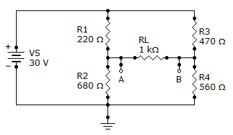
Options- A. 450 mV, 4.5 mA
- B. 4.50 V, 45 mA
- C. 4.50 V, 4.5 mA
- D. 450 mV, 45 mA Discuss
- 4. In a two-source circuit, one source acting alone produces 12 mA through a given branch. The other source acting alone produces 10 mA in the opposite direction through the same branch. The actual current through the branch is
Options- A. 22 mA
- B. 12 mA
- C. 10 mA
- D. 2 mA Discuss
- 5. If the steel disk in a crankshaft position sensor has stopped with the tab in the magnet's air gap, the induced voltage
Options- A. increases
- B. decreases
- C. is zero
- D. will remain constant Discuss
- 6. In an integrator, when the pulse width of the input is much less than the transient time, the output voltage approaches the shape of the input.
Options- A. True
- B. False Discuss
- 7. A 12 kΩ resistor is in series with a 0.02 µF capacitor across a 1.2 kHz ac source. If the current is expressed in polar form as I = 0.3∠0° mA, what is the source voltage expressed in polar form?
Options- A. 45.6 V
- B. 411.3 V
- C. 0.411 V
- D. 4.11 V Discuss
- 8. If the cross-sectional area of a magnetic field increases, but the flux remains the same, the flux density
Options- A. increases
- B. decreases
- C. remains the same
- D. doubles Discuss
- 9. Conversions between delta-type and wye-type circuit arrangements are useful in certain specialized applications.
Options- A. True
- B. False Discuss
- 10. Norton's theorem gives
Options- A. an equivalent current source in parallel with an equivalent impedance
- B. an equivalent current source in series with an equivalent impedance
- C. an equivalent voltage source in parallel with an equivalent impedance
- D. an equivalent voltage source in series with an equivalent impedance Discuss
More questions
Correct Answer: from south to north
Correct Answer: 4.8 V, 1.2 MΩ
Correct Answer: 4.50 V, 4.5 mA
Correct Answer: 2 mA
Correct Answer: is zero
Correct Answer: False
Correct Answer: 4.11 V
Correct Answer: decreases
Correct Answer: True
Correct Answer: an equivalent current source in parallel with an equivalent impedance
Comments
There are no comments.More in Electrical Engineering:
Programming
Copyright ©CuriousTab. All rights reserved.