Discussion
Home ‣ Electronics and Communication Engineering ‣ Automatic Control Systems See What Others Are Saying!
- Question
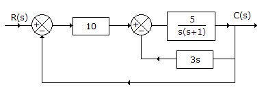
For the given figure,


Options- A.

- B.

- C.

- D.

- Correct Answer

ExplanationFor the inner loop, transfer function =
Then
 .
.
More questions
- 1. Match the following:
List I (VCR system) List II (Azimuth angle) A. VHS 1. 7° B. Video 2000 2. 15° C. Betamax 3. 6°
Options- A. A-1, B-2, C-3
- B. A-1, B-3, C-2
- C. A-3, B-1, C-2
- D. A-3, B-2, C-1 Discuss
Correct Answer: A-3, B-1, C-2
- 2. Match the following:
List I List II A. Copper 1. produces discrete energy level just above valence band B. Rubber 2. produces discrete energy level just below conduction band C. Antimony 3. large forbidden gap D. Boron 4. valence and conduction bands overlap
Options- A. A-1, B-2, C-4, D-3
- B. A-4, B-1, C-2, D-3
- C. A-4, B-3, C-1, D-2
- D. A-2, B-1, C-3, D-4 Discuss
Correct Answer: A-4, B-3, C-1, D-2
- 3. The number of doped regions in a SCR is
Options- A. 2
- B. 3
- C. 4
- D. 5 Discuss
Correct Answer: 4
Explanation:
p = n = p = n.- 4. In a half bridge inverter the gate pulses of the two thyristors have a phase displacement of
Options- A. 60°
- B. 90°
- C. 120°
- D. 180° Discuss
Correct Answer: 180°
- 5. A loss less line of characteristic impedance Z0 is terminated in pure reactance of -jZ0 value. VSWR is
Options- A. 10
- B. 2
- C. 1
- D. infinity Discuss
Correct Answer: infinity
Explanation:
A pure reactance does not absorb any power.Therefore VSWR is infinite because |rv| = 1.
- 6. A typical error rate on satellite circuits is one bit error in
Options- A. 107
- B. 103
- C. 102
- D. 1010 Discuss
Correct Answer: 107
- 7. In elemental dielectrics, the orientation and ionic polarization are absent.
Options- A. True
- B. False Discuss
Correct Answer: True
- 8. Which of the following should be used in order to prevent overloading or the last IF amplifier in a receiver?
Options- A. Variable selectivity
- B. Variable sensitivity
- C. Double conversion
- D. Squelch Discuss
Correct Answer: Variable sensitivity
- 9. The waveshape of output voltage of half bridge inverter is
Options- A. sinusoidal
- B. square
- C. triangular
- D. either (a) or (b) Discuss
Correct Answer: square
- 10. The main utility of SCR is due to
Options- A. gate triggering
- B. high temperature triggering
- C.
 triggering
 - D. high breakdown voltage Discuss
Correct Answer: gate triggering
Comments
There are no comments.
More in Electronics and Communication Engineering:
- 1. Match the following:
Programming
Copyright ©CuriousTab. All rights reserved.
