Discussion
Home ‣ Electronics and Communication Engineering ‣ Analog Electronics See What Others Are Saying!
- Question
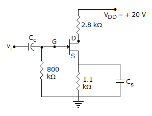
In figure ID = 4 mA. Then VS =

Options- A. 20 V
- B. 4.4 V
- C. 0.4 V
- D. 0.44 V
- Correct Answer
- 4.4 V
ExplanationVS = ISRS = 4 x 10-3 x 1.1 x 103 = 4.4 V.
More questions
- 1. The output frequency of a cycloconverter can be changed by changing the firing angle.
Options- A. True
- B. False Discuss
Correct Answer: False
- 2. Most of the memory chips in static RAM
Options- A. do not require any supply
- B. need 2 V supply
- C. need 5 V supply
- D. need 12 V supply Discuss
Correct Answer: need 5 V supply
Explanation:
Digital chips need 5 V supply.- 3. In crystalline solids, atoms are stacked in a regular manner.
Options- A. True
- B. False Discuss
Correct Answer: True
- 4. The classes of solid dielectrics are
Options- A. A, B, C, D, E, F, H
- B. A E B F H C D
- C. Y A E B F H C
- D. A E B F H C Discuss
Correct Answer: Y A E B F H C
- 5. The unit for mmf is
Options- A. A
- B. Wb
- C. T
- D. V Discuss
Correct Answer: A
- 6. In a single phase full wave regulator, the firing angles in the positive and negative half cycles are generally
Options- A. equal
- B. different
- C. equal or different
- D. different but sometimes equal Discuss
Correct Answer: equal
Explanation:
Firing angles are kept equal to get symmetrical output voltage.- 7. The real part of complex dielectric constant and tan? for a dielectric are 2.1 and 5 x 10⁻⁴ at 100 Hz respectively. The imaginary part of dielectric constant at 100 Hz is
Options- A. 1.05 x 10⁻³
- B. 2.1 x 10⁻³
- C. 5 x 10⁻³
- D. 1.05 x 10⁻² Discuss
Correct Answer: 1.05 x 10⁻³
Explanation:

- 8. The units for ?r are
Options- A. Farads
- B. Farads/m
- C.

- D. no units Discuss
Correct Answer: no units
Explanation:
?r is only a numeric. Hence no units.- 9. Tesla is a unit of
Options- A. flux
- B. field strength
- C. flux density
- D. MMF Discuss
Correct Answer: flux density
- 10. In a receiver, which of the following device has IF input but RF output?
Options- A. Demodulator
- B. Loudspeaker
- C. Audio amplifier
- D. Frequency changer Discuss
Correct Answer: Demodulator
Comments
There are no comments.
More in Electronics and Communication Engineering:
Programming
Copyright ©CuriousTab. All rights reserved.
