CuriousTab |
CuriousTab
Discussion
Home ‣ Electronics and Communication Engineering ‣ Analog Electronics Comments
- Question
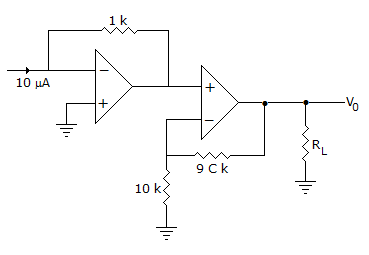
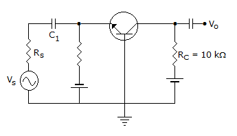
The output V0 in figure is
Options- Correct Answer
- -100 mV
ExplanationInput to non-inverting op-amp is -10 x 10-6 x 103 = -10 mV.Therefore output =
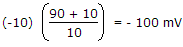 = -100 mV.
Analog Electronics problems
Search Results
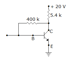
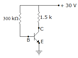
- 1. In figure, VEB = 0.6 V, ? = 99. Then VC and IC are
Options
Discuss
Correct Answer: 9.3 V and 1.98 mA respectively
Explanation:
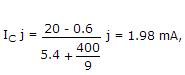
VC = 20 - 1.98 x 10-3 x 5.4 x 103 ≂ 9.3 V.
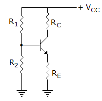
- 4. In figure what is value of IC if ?dc = 100. Neglect VBE
Options
Discuss
Correct Answer: 10 mA
Explanation:
Since IB = 100 ?A, IC = ?IB = 10 mA.- 5. In figure the saturation collector current is
Options- A.

- B.

- C.
 Discuss
Correct Answer:
Explanation:
Since IE ≂ IC, .
.
- 7. Study the circuit of figure and examine the following statements
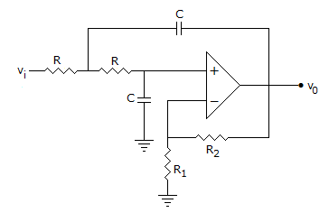
- It is an active low pass finer.
- It is a second order filter.
- The change in gain is 40 dB/decade.
Options
Discuss
Correct Answer: 1, 2 and 3
Explanation:
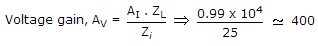
The circuit is a second order active low pass filter for which gain is 40 dB/decade.- 8. The 'h' parameters of the circuit shown in the figure are hib = 25 ?, hfb = 0.999 and hob = 10-6? The Voltage gain is
Options
Discuss
Correct Answer: 4
Explanation:
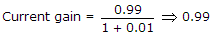
Zi = 25 + 10-6 x 0.99 x 104 ⟹ 25
 .
.
Comments
There are no comments.
- 1. In figure, VEB = 0.6 V, ? = 99. Then VC and IC are